
Relationship among coordinate systems. The matrix underneath each stage determines the transformation applied at that stage for the perspective and parallel projections.
| 8.Viewing |
![[prev]](common/prev.gif)
![[next]](common/next.gif)

Relationship among coordinate systems. The matrix underneath each stage determines the transformation applied at that stage for the perspective and parallel projections. |
Workstation Transformation(window to viewport mapping)
|
Workstation Transformation(window to viewport mapping)
Steps: 1. Translate lower left corner to origin: T(1,1,0) |
Workstation Transformation(window to viewport mapping)
Steps: 1. Translate lower left corner to origin: T(1,1,0) 2. Scale to correct size: |
Workstation Transformation(window to viewport mapping)
Steps: 1. Translate lower left corner to origin: T(1,1,0) 2. Scale to correct size: 3. Translate into place: |
View VolumesView volume bounded by front and back planes, and by top, bottom, and side planes. Front and back planes are parallel to the view plane at positions zfront and zback along the zv axis.
|
View VolumesView volume bounded by front and back planes, and by top, bottom, and side planes. Front and back planes are parallel to the view plane at positions zfront and zback along the zv axis.
|
View VolumesView volume bounded by front and back planes, and by top, bottom, and side planes. Front and back planes are parallel to the view plane at positions zfront and zback along the zv axis.
|
View VolumesView volume bounded by front and back planes, and by top, bottom, and side planes. Front and back planes are parallel to the view plane at positions zfront and zback along the zv axis.
|
World and View Spaces
|
World and View Spaces
|
World and View Spaces

|
World to View TransformationAligning a viewing system with the world-coordinate axes using a sequence of translate-rotate transformations.
|
World to View TransformationAligning a viewing system with the world-coordinate axes using a sequence of translate-rotate transformations.
Translate view point to origin of world coordinate space. |
World to View TransformationAligning a viewing system with the world-coordinate axes using a sequence of translate-rotate transformations.
Rotate to align view coordinate axes (xv,yv,yv) with world coordinate axes (xw,yw,yw). |
Two different projections of the same line
|
Simple parallel transformation (orthographic)View plane is normal to direction of projection: |
Simple perspective transformation
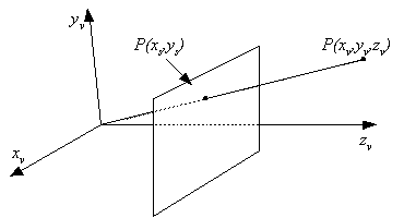 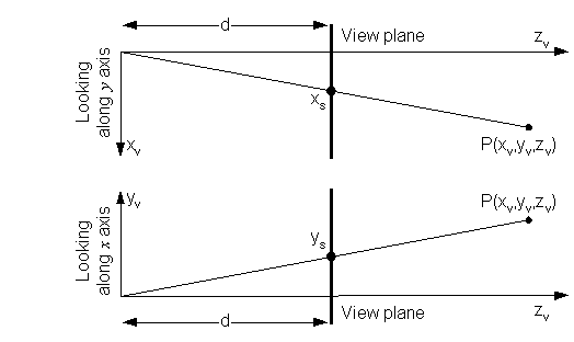
|
Simple perspective transformation
|
Simple perspective transformation
|
Simple perspective transformation
|
Simple perspective transformation
xs = x/w, ys = y/w,zs = z/w = d |
Basic Viewing System
Viewing system using a camera position, a viewing direction vector N, an up vector V, and an optional vector U. The world coordinate system is right handed, the view coordinate system is left handed. |
Basic Viewing System
Viewing system using a camera points, a viewing direction vector N, an up vector V, and an optional vector U. The world coordinate system is right handed, the view coordinate system is left handed. |
Basic Viewing System
Viewing system using a camera points, a viewing direction vector N, an up vector V, and an optional vector U. The world coordinate system is right handed, the view coordinate system is left handed. |
Basic Viewing SystemImplementation
|
Basic Viewing SystemImplementation
|
Basic Viewing SystemImplementation
|
View Transformation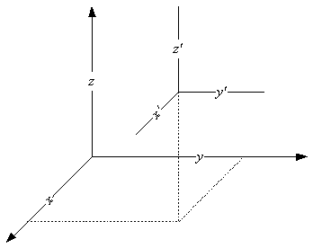
1. Translate origin of world coordinate system to origin of view coordinate system. (Transformation of coordinate system is inverse of that which moves points) |
View Transformation
1. Translate origin of world coordinate system to origin of view coordinate system. (Transformation of coordinate system is inverse of that which moves points) 
|
View Transformation
2. Rotate coordinate system 90o about x' axis. Use
|
View Transformation
2. Rotate coordinate system 90o about x' axis. 
|
View Transformation
3. Rotate about y' by |
View Transformation
3. Rotate about y' by 
|
View Transformation
4. Rotate about x' by |
View Transformation
4. Rotate about x' by 
|
View Transformation
5. Reflect z' axis to create left-handed coordinate system. |
View Transformation
5. Reflect z' axis to create left-handed coordinate system. 
|
View Transformation
6. Twist about z' so that y' aligns with V |
View Transformation
6. Twist about z' so that y' aligns with V 
|
Viewing Example
|
Viewing Example
1. Translate world origin to view origin
|
Viewing Example2. Rotate 900 about x'.
|
Viewing Example3. Rotate about y' by
|
Viewing Example4.Rotate about x' by 
|
Viewing Example5. Reflect z' axis to create left-handed coordinate system.
|
Viewing Example6. Twist about z' so that y' aligns with V
|
Viewing ExampleMultiply it all together 
|
Viewing ExampleCube at origin
|
|||||||||||||||||||||||||||||||||||||||||||
Compositions of Translations and RotationsResulting matrix has form 
|
Basis Rotation Shortcut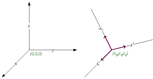
Where u'x,u'y,u'z are unit basis vectors |
Basis Rotation Shortcut
Where u'x,u'y,u'z are unit basis vectors Assume we've already performed translation, so x'0=0, y'0=0, z'0=0 |
Basis Rotation Shortcut
Where u'x,u'y,u'z are unit basis vectors Assume we've already performed translation, so x'0=0, y'0=0, z'0=0 Can rotate to align basis vectors using |
Applying the shortcutGiven view direction vector N Given view up vector V |
Shortcut Example
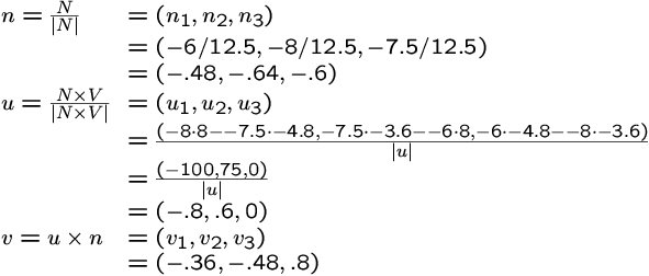
|
Shortcut Example


|
Clipping for Basic View System

|
Advanced Viewing System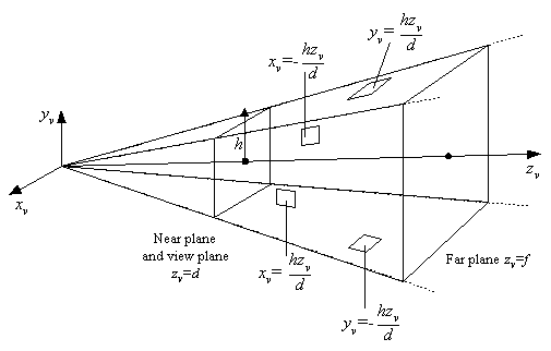
Advanced Viewing system: view frustum formed by six planes and the view volume. This is a left-handed coordinate system. |
Advanced Viewing SystemRequirements
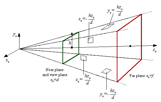
Advanced Viewing system: view frustum formed by six planes and the view volume. This is a left-handed coordinate system. |
Advanced Viewing System

Advanced Viewing system: view frustum formed by six planes and the view volume. This is a left-handed coordinate system. |
Advanced Viewing System

Advanced Viewing system: view frustum formed by six planes and the view volume. This is a left-handed coordinate system. |
Advanced Viewing System

Advanced Viewing system: view frustum formed by six planes and the view volume. This is a left-handed coordinate system. |
Advanced Viewing SystemView volume specified by: (two sides) (two sides)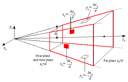
Advanced Viewing system: view frustum formed by six planes and the view volume. This is a left-handed coordinate system. |
Advanced Viewing SystemView volume specified by: (two sides) (two sides) (top and bottom) (top and bottom)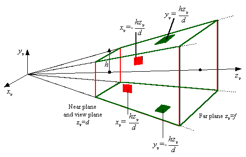
Advanced Viewing system: view frustum formed by six planes and the view volume. This is a left-handed coordinate system. |
Advanced Viewing SystemView volume specified by: (two sides) (two sides) (top and bottom) (top and bottom) (near and far) (near and far)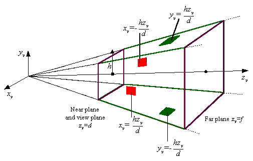
Advanced Viewing system: view frustum formed by six planes and the view volume. This is a left-handed coordinate system. |
Advanced Viewing SystemView volume specified by: (two sides) (two sides) (top and bottom) (top and bottom) (near and far) (near and far)View plane has dimensions: 2h x 2h 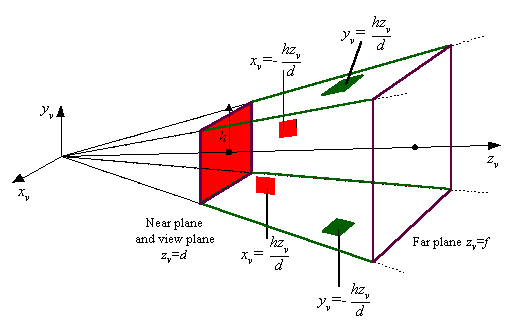
Advanced Viewing system: view frustum formed by six planes and the view volume. This is a left-handed coordinate system. |
Projection for Advanced View System (part 1)Want 3D screen space because it facilitates:
Chose Zs such that:
|
Projection for Advanced View System (part 1)Want 3D screen space because it facilitates:
Chose Zs such that:
Satisfied for: |
Projection for Advanced View System (part 1)Want 3D screen space because it facilitates:
Chose Zs such that:
Satisfied for: |
Projection for Advanced View System (part 2)Full perspective transformation
|
Projection for Advanced View System (part 2)Full perspective transformation
Using a homogeneous coordinates: |
Projection for Advanced View System (part 2)Full perspective transformation
Using a homogeneous coordinates: |
Projection for Advanced View System (part 3)
|
Projection for Advanced View System (part 3)
|
Projection for Advanced View System (part 3)
|
Projection for Advanced View System (part 3)
|
Clipping for Advanced View SystemClipping against view frustum necessary because:
|
Clipping for Advanced View SystemClipping against view frustum necessary because:
Clipping cases:
|
Clipping for Advanced View SystemClipping against view frustum necessary because:
Clipping cases:
Clip in homogeneous coordinates (before perspective divide)
to: |
![[prev]](common/prev.gif)
![[next]](common/next.gif)
| Made by dynaPage 0.2 |